Doppelgänger RFID Dev Board
Intent
The Doppelgänger RFID Development Board serves two primary purposes:
- A hardware platform for running Doppelgänger Core in long-range badge cloning operations.
- An open-source project specifically built for RFID enthusiasts.
We designed this board with RFID tinkerers in mind. No more frabricobbling endless logic-level shifters, power circuits, or overcrowded development boards.
- Want to build a mock door controller that sends GPIO signals to release a maglock? Route GPIO35/36 to an IoT relay.
- Want to trigger haptic feedback on badge reads? Wire it up…
Hardware Design
The Doppelgänger RFID Development Board includes the following built-in features:
| Item | Notes |
|---|---|
| ESP32-S3-MINI-1-N8 | Espressif Datasheet |
| USB-C w/ ESD Protection | Supports flashing and serial communication/debugging |
| Voltage Divider | Allows safe processing of Wiegand data on D0/D1 |
| Dual Input 12V → 5V LDO | The LM1117 safely steps down the 12V input to 5V (via 5.5mm x 2.1mm barrel plug or 2-pin screw terminal) |
| 5V → 3.3V LDO | The TLV755P converts 5V (from Power In or USB-C) to 3.3V to power the ESP32 |
| General Purpose LED (Blue) | User-configurable through code |
| Power LED (Red) | Indicates that the ESP32-S3 is receiving stable power |
| Power/GND Output | Pass-through power output-whatever voltage is supplied on input is passed through |
| Wiegand Interface | Connect DATA0 & DATA1 from your RFID reader via the screw terminal connectors |
| External GPIO | Access GPIO35 and GPIO36 for external device integration |
| +3.3V & +5V Output | Need to power other devices? We’ve got you covered. |
| Boot & Reset Buttons | Dedicated buttons for flashing and resetting the board |
| Mounting Hardware | Includes all required hardware for safe, secure mounting |
Wiring Diagrams
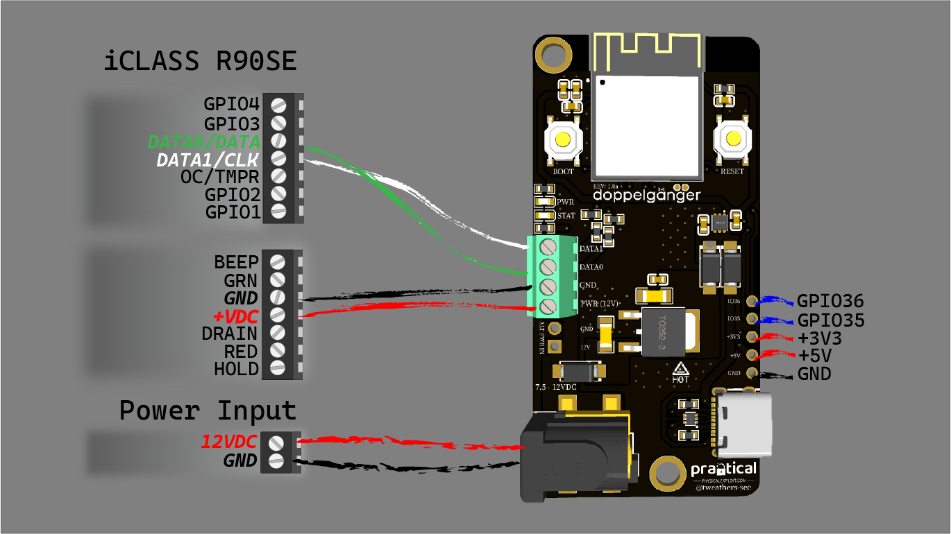
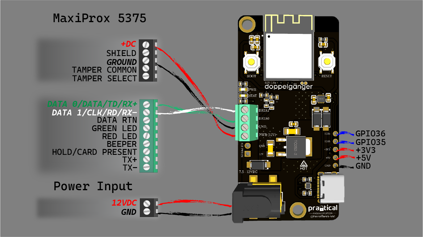
We recommend using 22 AWG solid wire for connections between the Doppelgänger RFID Development Board and your reader. Additionally, secure your power cables with strain relief to prevent unintentional damage from pulling or tension. An adhesive-backed zip-tie mount works great for this purpose.
Warning: Do not supply more than 12VDC to the Doppelgänger RFID Development Board. Overvoltage may result in overheating or fire. We will not replace any board damaged due to improper wiring or voltage misuse. As the user, you assume all risks when operating the Doppelgänger RFID Development Board. If you’re not confident wiring the board to a reader, consider purchasing a pre-assembled unit from the Physical Exploitation Store.
R90SE with Doppelgänger RFID Development Board
MaxiProx with Doppelgänger RFID Development Board
Firmware & Flashing
Firmware Compatibility
This development board is designed exclusively for Doppelgänger Core firmware. The latest firmware version (1.1.0) includes support for HID H800002 46-bit and Avigilon Avig56 56-bit card formats.
FIRMWARE COMPATIBILITY WARNING:
ONLY use Doppelgänger Core firmware with this development board.
DO NOT flash firmware from:
- Doppelgänger Breakout Board (End-of-life)
- Doppelgänger Pro (End-of-life)
- Doppelgänger Community (End-of-life)
- Stealth v1 or v2 devices
Cross-flashing incompatible firmware will cause operational issues and may render the device inoperable.
Flashing Instructions
For detailed instructions on flashing firmware, refer to the Flashing & Updating section of the documentation.
Download the latest Doppelgänger Core firmware from the GitHub Releases page.